
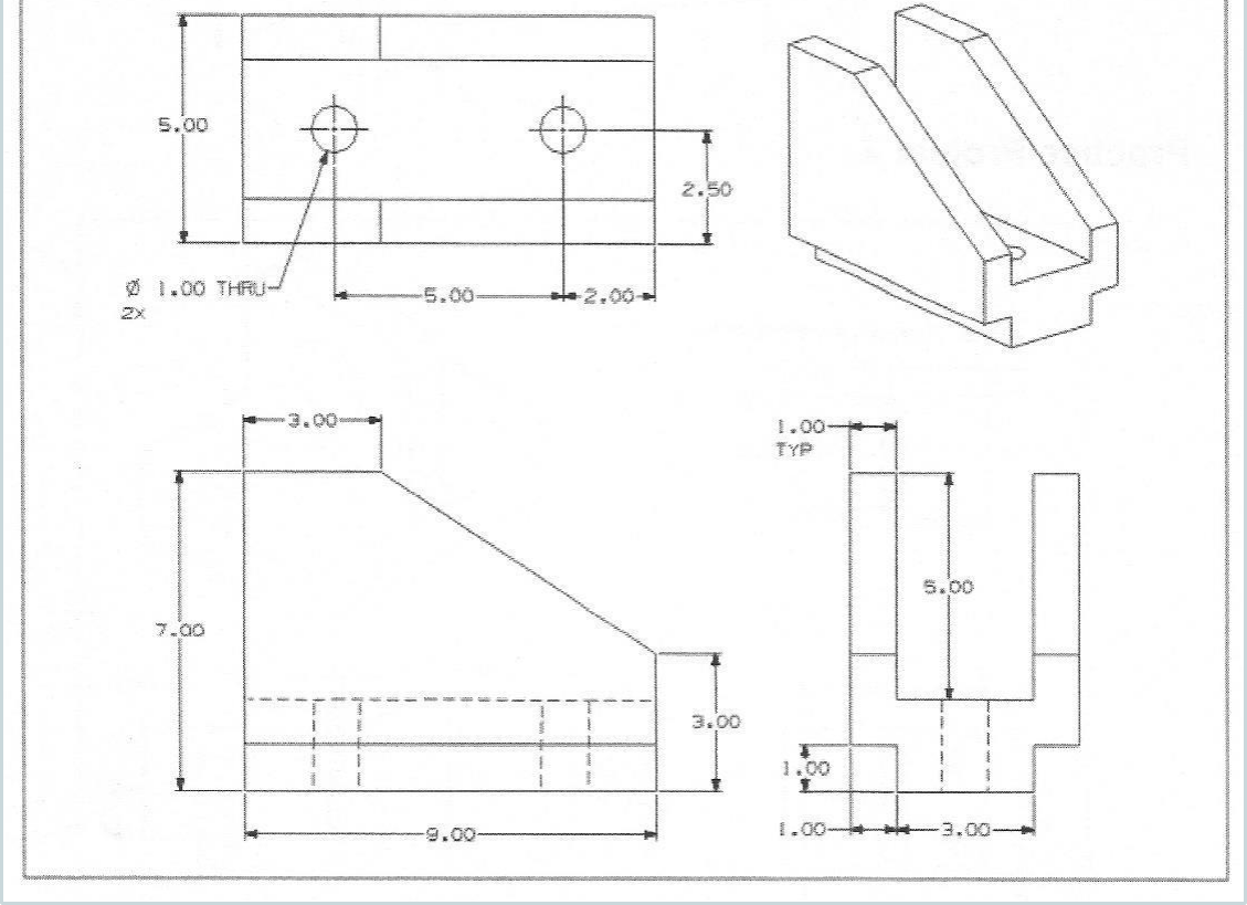
Your task: create one solid body that matches the dimensioned views. Decide how to organize the base, sloped side profile, central channel, and two through holes.
NX skills and commands involved
Modeling requirements
- Work in inches and follow the dimensions shown on the drawing.
- Create a single finished solid body.
- Use dimensional and geometric constraints instead of visually approximating the sketch.
- Keep the two holes aligned and defined by design intent; mirror or pattern them if your feature plan supports it.
- Name the major features so another NX user can understand the model sequence.
- Do not trace the isometric view. Use the orthographic views as the dimensional authority.
Progressive hints
Try the challenge without help first. Open only the next hint you need.
Hint 1 · Choose the controlling view
The side view carries the overall length, rear height, front height, and sloped transition. It is a strong candidate for the first controlling sketch.
Hint 2 · Separate shape from material removal
Build the complete outer envelope first. Treat the central U-shaped channel as a separate subtractive feature so the model remains easier to edit.
Hint 3 · Control the channel symmetrically
The end view shows a 1.00–3.00–1.00 width arrangement. A centered sketch or symmetric constraints will preserve equal side walls.
Hint 4 · Add the holes late
Place the two Ø1.00 THRU holes after the main form and channel are stable. Use the top view dimensions to locate their centers.
Recommended feature sequence
- Create the main side-profile sketch. Constrain the overall 9.00 length, 7.00 rear height, 3.00 front height, 3.00 upper flat, and the sloped transition shown.
- Extrude the outer profile. Use the overall width from the end and top views to form the full solid envelope.
- Create the central channel. Sketch the U-shaped removal symmetrically, preserving the two 1.00 side walls around the 3.00 opening.
- Form the lower step. Use the 1.00 dimensions in the end and side views to reproduce the base relief accurately.
- Add the two through holes. Create Ø1.00 THRU holes and locate their centers using the top-view spacing and offsets.
- Inspect the feature tree and measure. Confirm the critical dimensions, one solid body, and a clean sequence before considering the exercise complete.
Download the exercise sheet
Keep the original Practice Project 01 drawing open beside NX or print it for a distraction-free modeling session.
Download PDF exercise sheet ↓Final self-check
- One solid body remains in the model.
- Overall length is 9.00 and overall width is 5.00.
- Rear and front heights match the 7.00 and 3.00 dimensions.
- The upper flat and sloped transition match the side view.
- The channel is centered with the 1.00–3.00–1.00 width arrangement.
- Both Ø1.00 holes are through holes and match the top-view locations.
- The lower step matches both the side and end views.
- Sketches are constrained and major features are sensibly named.
- The finished form agrees with the isometric reference from every view.
Build the complete Siemens NX workflow.
Essential NX CAD covers the interface, sketches, part features, assemblies, drafting, advanced modeling, and ten practice projects.
Explore the complete Essential NX CAD guide →